Benchwork Backbone
My definition of the backbone is everything that comes out from the wall to allow the placement of risers onto which the subroadbed will be laid.
L-Girder Supports
I wanted to have no legs supporting the benchwork out by the aisle. So I came up with the cantilevered design shown here, which is quite strong. I used white pine for the 2×4’s and 2×2’s, and poplar for all other parts. This diagram shows most of the types of supports I used to hold the L-girders.
Vertical Wall Members
The benchwork’s cantilevered design causes the horizontal load bearing members to try to pull away from the vertical wall members to which they are attached. To counteract this force, I used 3 different designs to securely fasten the vertical wall members to existing framework that was known to be secure.
Design (1)
A 2×4 was fastened to the existing wall with lag bolts, with the wide face against the wall.
A second 2×4 was screwed to the first one, with its wide face against the narrow edge of the first. I used several large torx-head wood screws to secure it.
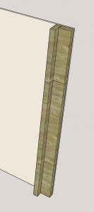
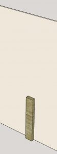
Design (2)
Like Design (2), I first secured a 2×4 with lag bolts to the existing wall, with its wide face against the wall. However, in this case, I did not fasten a second 2×4.
This design is not quite as strong as Design (1) but it does project out a bit less.
Design (3)
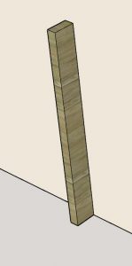
I only used this design where I had built the half-wall down the middle of the layout. With the 4-foot 2×4 already vertical, it was ready for the horizontal members to be securely attached.
This design is just as strong as Design (1) because the horizontal members will be screwed to the wide face of the 2×4.
Horizontal Support Joists
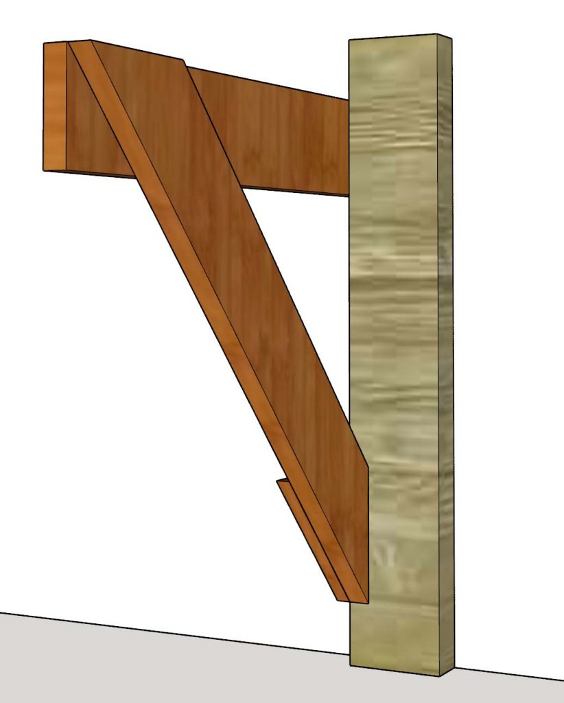
These joists support all the weight of the layout and thus I designed them for strength. All of the designs are anchored to a vertical member and have a horizontal member on which L-girders will rest. How far out can you go? Some horizontal members extend 24″ from the wall and remain very solid. The key is having an angled support brace that carries the load back to the vertical member.
Design (1)
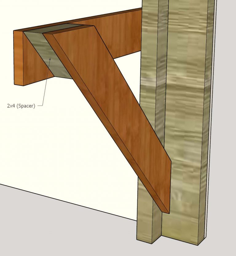
This is the strongest design. The horizontal 1×4 is screwed to the wide face of a 2×4 that’s not going to move. I can put as many screws as I want to keep it secure.
The angled 1×4 ideally is at a 45 degree angle although you can fudge if you need to. It is screwed to the 2×4 vertical member with several screws. The horizontal and angled 1×4’s are joined by a custom-cut 2×4 spacer block that is screwed to both members.
The further out the angled 1×4 goes, the more support is provides. But it’s not necessary to take it all the way to the end of the horizontal member.
Design (2)
I used this option when I didn’t have the extra space needed to attach the second 2×4 vertical member.
The horizontal member is screwed to the 2×4 vertical member but to the edge instead of the wide face.
A gusset made of a 1×4 is used to secure the angled 1×4 on the wide faces.
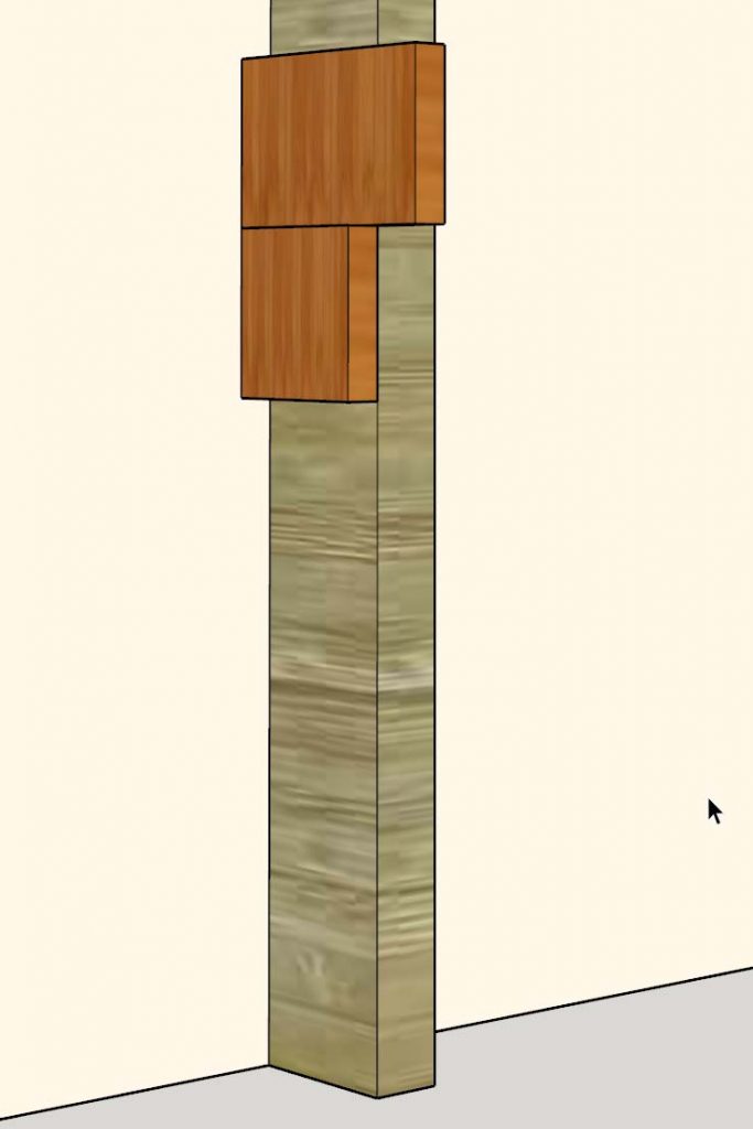
Design (3)
I used this design when I had very little horizontal space that I needed to span.
The top 1×4 juts out only a short distance and is screwed to the flat face of the 2×4.
A second 1×4 is cut to just the width of the 2×4 and placed immediately under the top one. This piece simply adds extra strength to compensate against potential rotation of the horizontal members.
This might be unnecessary but I tend to overbuild things.
L-Girders
I secured L-girders, each made of 2 1×3’s, to the top of the L-girder supports. The L-girders run roughly parallel to the direction of the track plan.
An actual L-girder is very simple in design. It’s just 2 long strips of 1x stock, screwed and glued to form an L-shape profile. I used 2 1×3’s for both parts.
The vertical part is strong enough to span any reasonable distance. I like using a 1×3 for the horizontal part because it gives me extra room on the underside to screw in to stuff above it.
I orient the L-girders with the vertical member away from the front of the layout to make it easier later to screw in stuff from underneath.
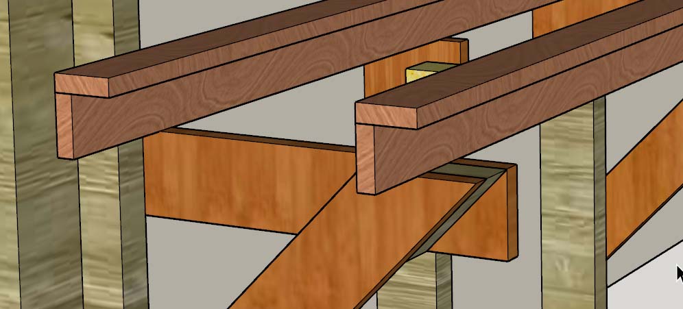
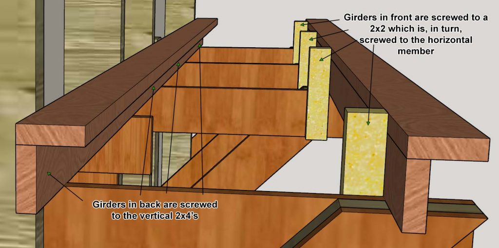
The L-girders must be secured to some vertical members.
If an L-girder is positioned at the back of the layout, I screwed it to the protruding 2×4’s.
For an L-girder that was positioned towards the front of the layout I cut out a piece of 2×2, oriented it vertically and screwed it to the face of a horizontal member.
