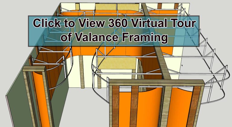
Valance Framing
Horizontal Members
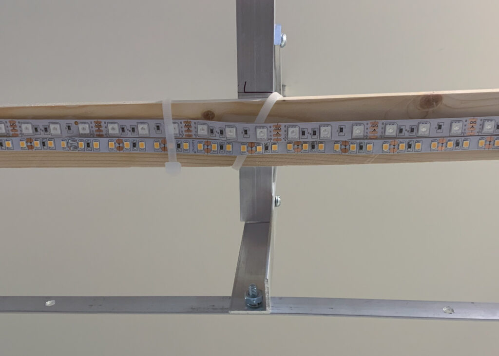
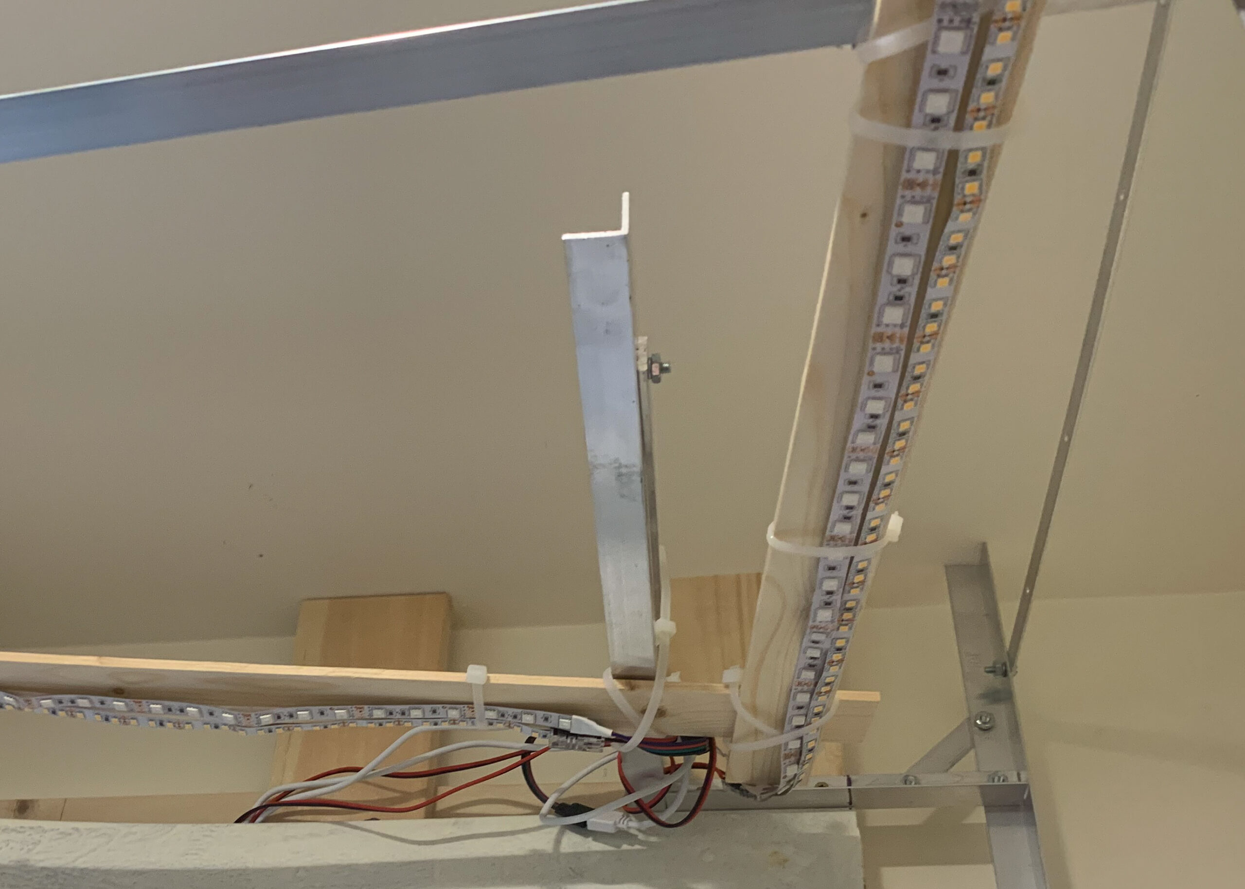
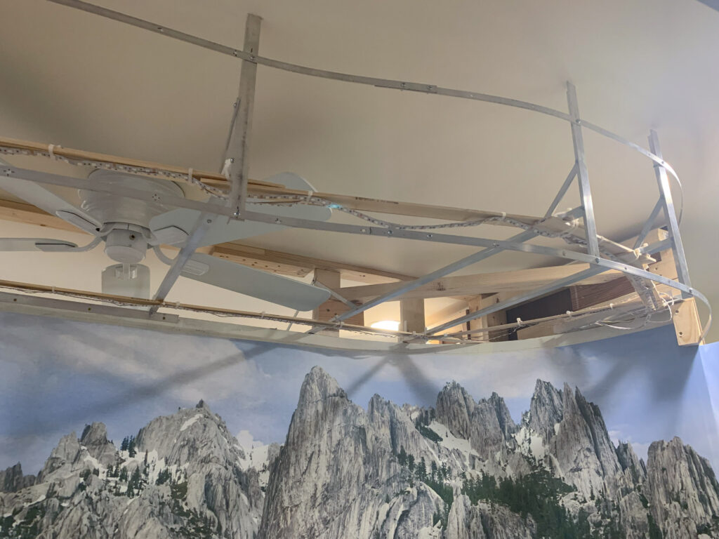
Since the frame needs to support only the weight of the valance wall, the wooden slats for the lights and the lights themselves, I used a cantilevered design for the horizontal members, which were made of aluminum angle (3/4″ x 3/4″ x 1/16″). Notice in the photos below that one end of the horizontal angle member is screwed or bolted to a secure location, like a 1 x 4 or another secured angle member and is kept horizontal by a piece of aluminum flat bar (1/2″ x 1/16″) secured at a higher location with screws or bolts. To determine how far out each member goes, I needed to consult the track plan. To ensure that the front of the layout was properly lit, I placed the edge of the valance 3 inches further out and into the aisleway than the edge of the layout. In hindsight, the left part of the layout’s lighting valance would have been easier to build if I had just installed the suspended ceiling panels over the entire left part. However, that would have been more expensive. Also, when you’re standing in the aisleway, you are standing in a much darker area than the layout itself so it is a bit more dramatic.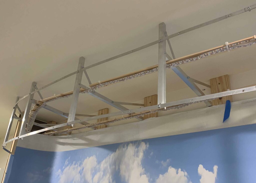
Vertical Members
The vertical members act as the positioning stops for the outside runners. While both the vertical and horizontal members initially have a lot of play, once everything is bolted in place, all the pieces keep each other steady.
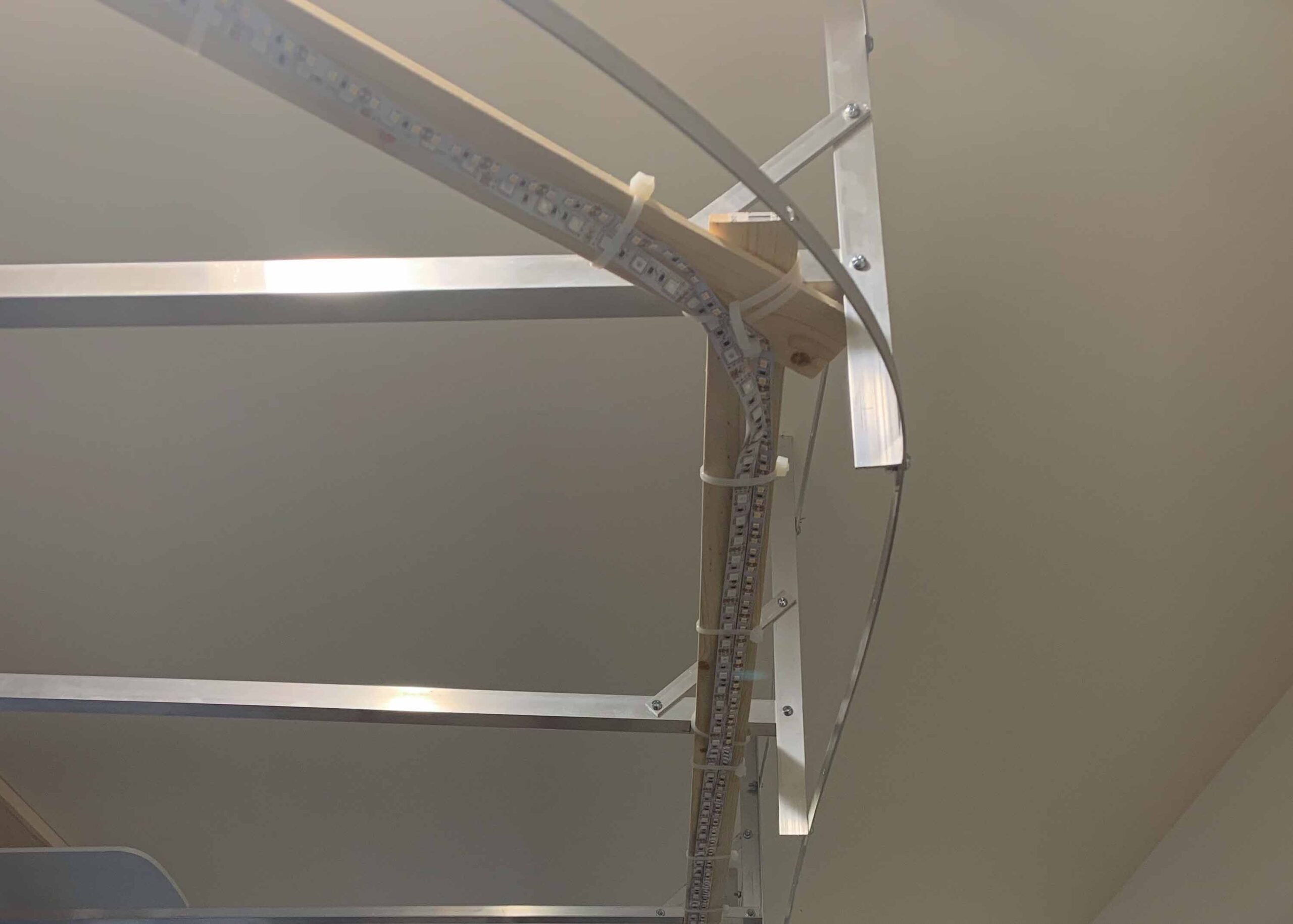
In these photos, note that each vertical member is made of the same material as the horizontal members and is attached to the “free” end of a horizontal member with a bolt/nut. It is held vertical by an slanted piece of aluminum flat bar bolted to the same horizontal member.
Outside Runners
The “outside runners” are the 2 horizontal runs of aluminum bar that gently bend to form the outside perimeter of the valance’s border. Being made of 1/2″ x 1/16″ aluminum flat bar, the runners can be bent without breaking and are just stiff enough to hold their shape. When I had to splice 2 pieces end to end I overlapped them and put 4 screw/nuts in the 2 pieces, 2 on each piece.
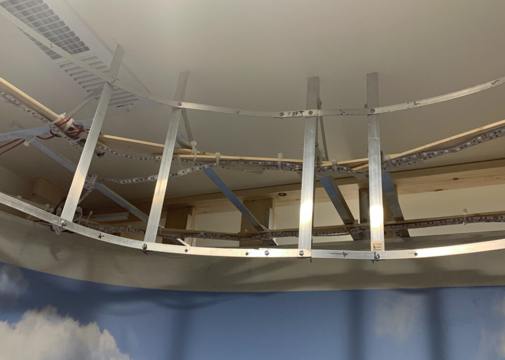
Two runners are needed to securely fasten the masonite valance skin. The runners are attached to the vertical members with screw/nuts. Note that the sides of the vertical members don’t always sit flush against the side of the runners. That causes no issues. I just needed the vertical member to be tight against some part of the runner.
Lighting Slats
As can be seen in many of the photos, the LED ribbon lights are attached to 1/8″ thick wooden slats that have been secured to the horizontal members with zipties. I cheated sometimes and attached one slat to another if the gap was just a few inches. By using zipties and cheap wooden slats, I could, if necessary, re-arrange things cheaply and easily as I progressed through the rest of the installation.
So, where did I locate them and how many did I install? One length of slats follow the path of the outside runners and is located about 4″ in from the edge. Another length follows the path of the backdrop and is located about 4″ away from the backdrop panel. On the widest section, I installed one extra length of slats between the “inner” and “outer” line of lights to allow for an extra length of warm white LED lights.
