Traverser Build Out
The video below describes the steps I went through to build the traverser. The comments sections contains links to important information you’ll need to complete the build.
The following is a summary of the constructions steps.
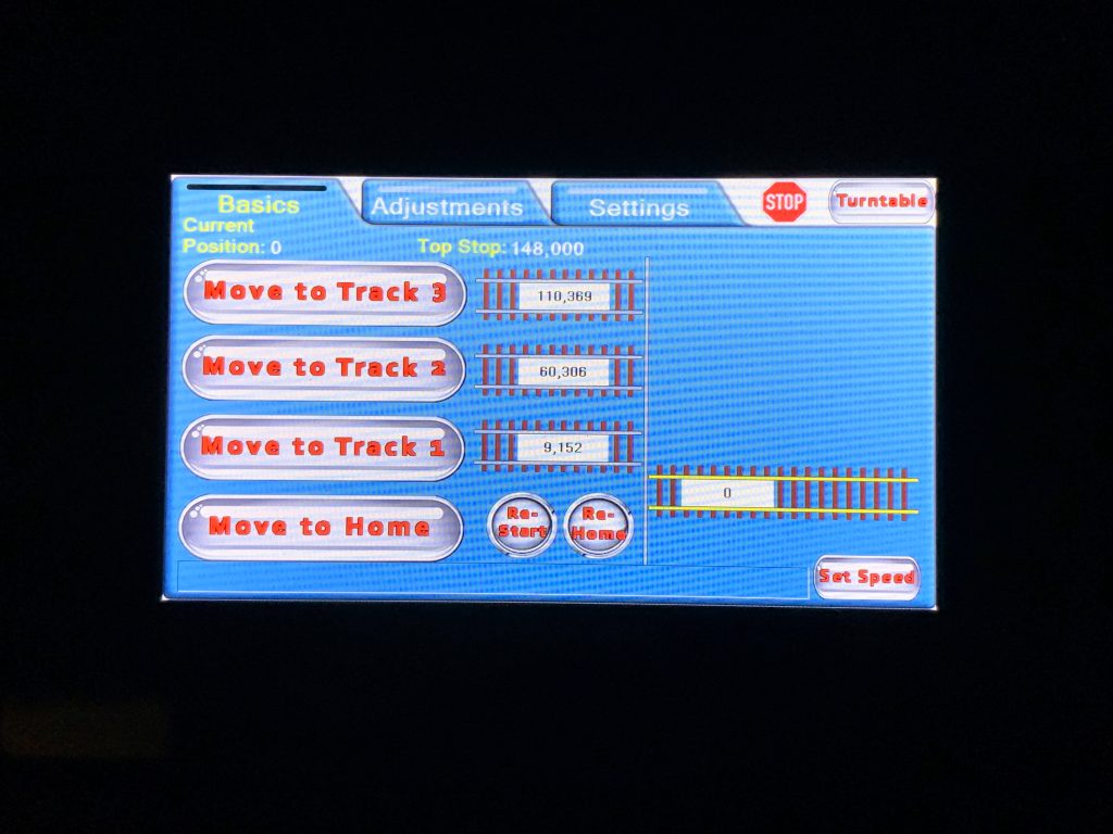
Design the Control Panel User Interface
The user interacts with the control system via a touchscreen device called a Nextion display. You design the interface with software on your computer and then upload it to the device.
The main control program, stored on an Arduino microcomputer, detects when the graphical buttons on the Nextion are pushed and responds by updating the display screen.
The video has a link to the configuration file I created.
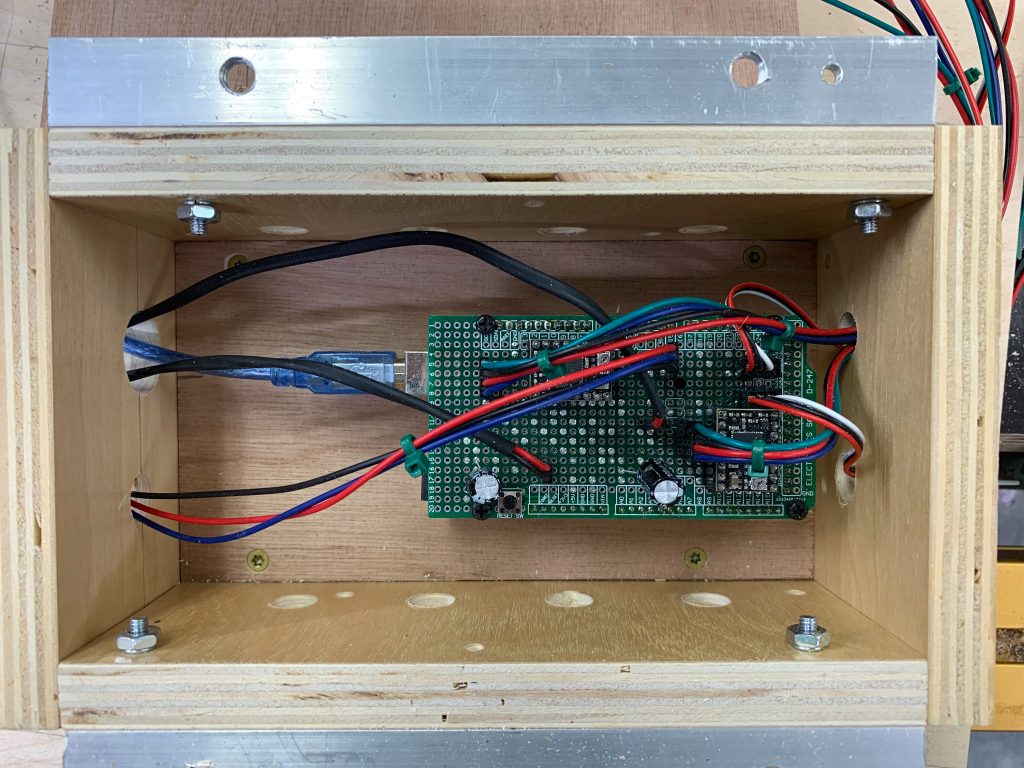
Build Control Circuit
The table is moved by a stepper motor. A custom program stored on an Arudino microcomputer controls that movement, in response to input from the Nextion display.
The circuit is not complicated but the program is fairly complex. The video has a link to the program I wrote.
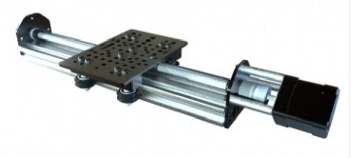
Build Linear Actuator
I use this linear actuator, available in kit form, to translate the rotary movement of the stepper motor to lateral movement. Because the kits only come in certain sizes, you should build and test your kit now, to make sure it will move the table far enough.
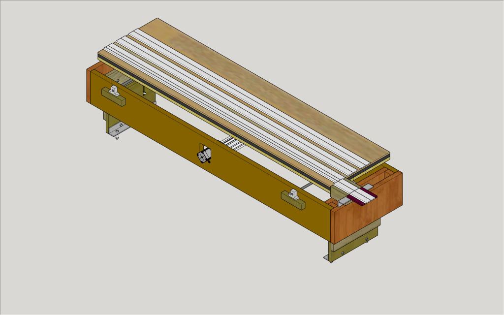
Draw Detailed Plans
After building the linear actuator, you can determine the width of the table frame and the width of the tabletop.
Then, you should draw as detailed a set of plans as you can. I used Sketchup. The video has a link to my model.
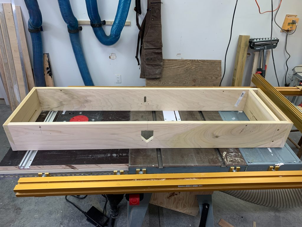
Build Frame
The frame is built from 1×6 poplar. The build process has some tricky parts like “match drilling” some holes and cutting out some funky looking holes in some fairly precise locations. The video has some details on the tricky parts.
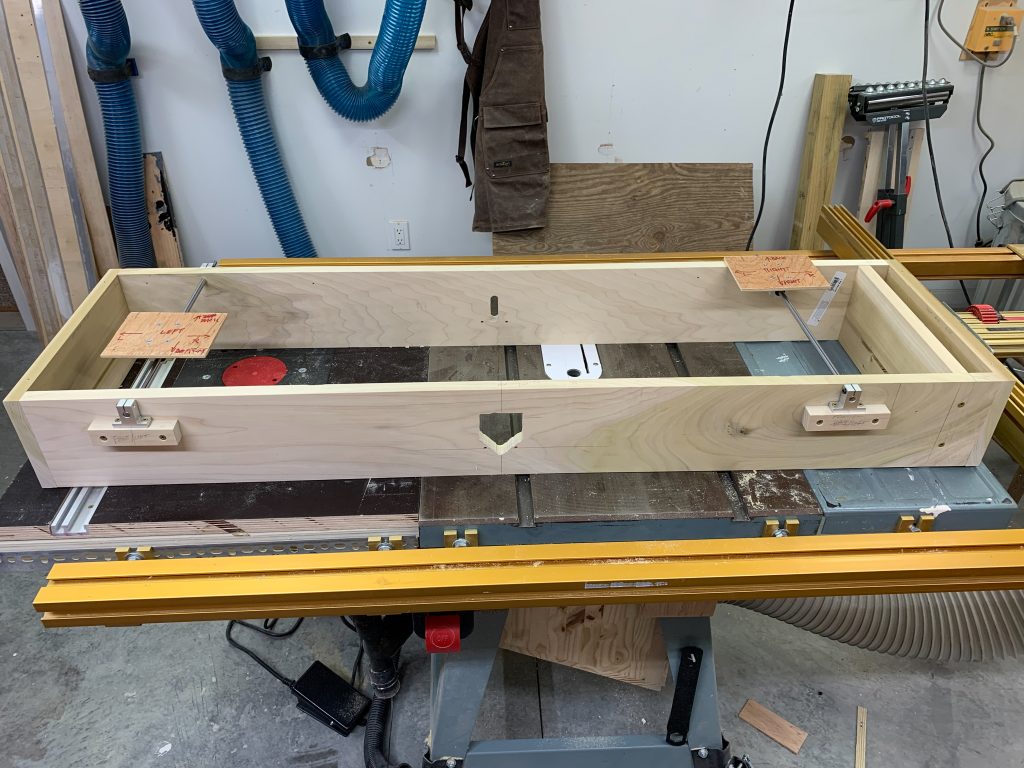
Build and Install Bearing Plates
2 “bearing plates” are installed to bear some of the load of the table as it moves. The flat plates, made of a couple pieces of wood, are screwed to a “bearing block”, which slides on chrome rods.
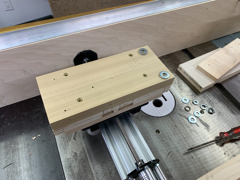
Install Linear Actuator
The linear actuator is attached to the frame using 4 machine screws. Extra wood is attached to the “gantry plate” so that it reaches up to the level of the tabletop.
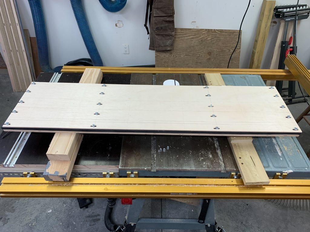
Build the Tabletop
The tabletop has 3 layers. The top layer can slide left and right because slots are routed into it. The bottom layer is sponge foam rubber that can compress a bit when the bolts are tightened, thus allowing for some vertical fine-tuning. The bottom layer is stiff plywood.
Attach Tabletop to Frame
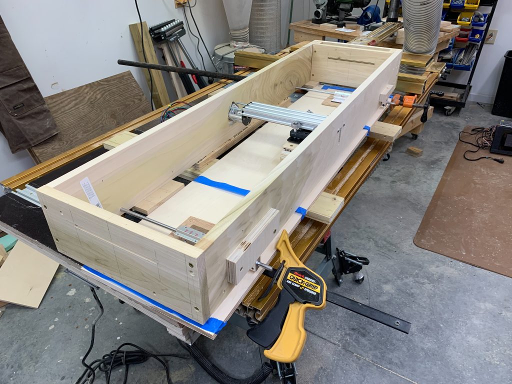
This is a critical process. With all the parts upside down, and clamped into position, the 2 bearing plates and the linear actuator are screwed to the underside of the tabletop. Fairly precise positioning is done before one commits to the final screw-ins.
Install Optical Detector
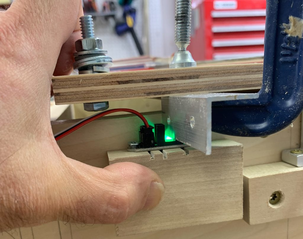
The control program needs to be able to detect when the table has reached a known, fixed position, also known as the “home stop”. The video shows how to build a base for an optical detector unit and position it so that it “lights up” when the home position is reached.
Lay Track
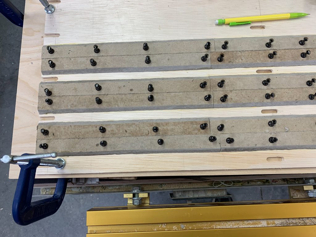
I used homemade homasote strips and PECO flextrack to provide the running rails for the 3 tracks. Just standard tracklaying stuff here.
Build and Install Transition Track
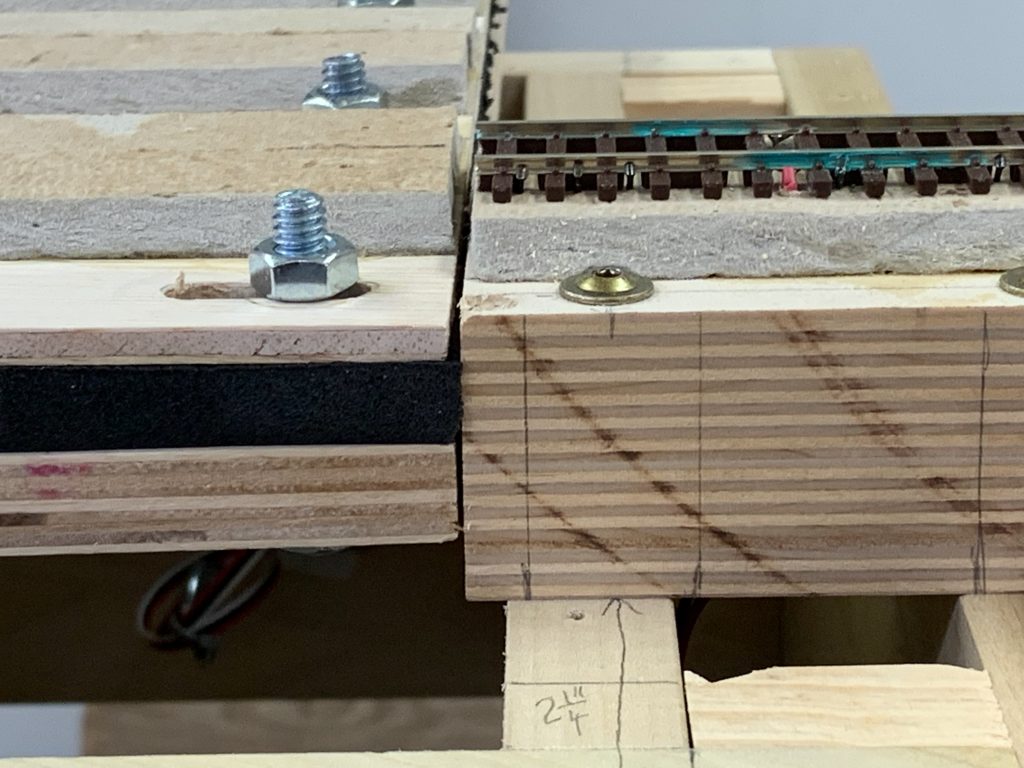
The tabletop aligns with the “transition track” to let the trains enter and exit the table. Building this small section of track, along with its base, is not difficult but it requires careful cutting and alignment.
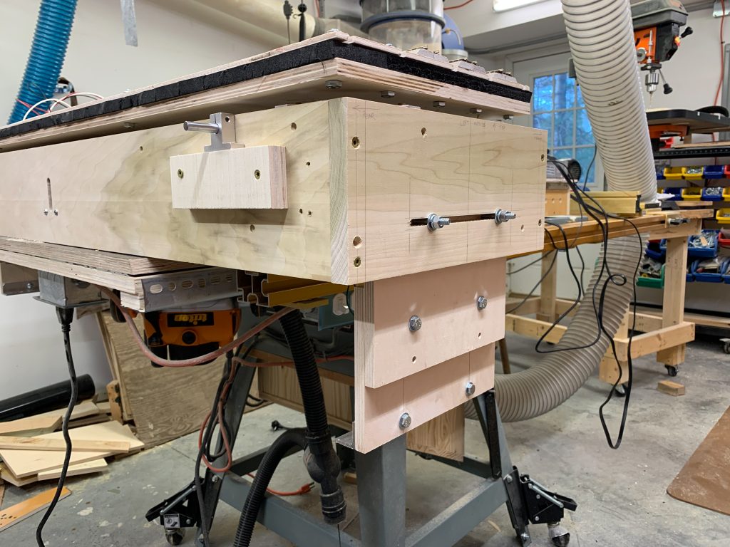
Build and Attach End Supports
At each end of the table, we attach a vertical support to raise the table up to the level of the existing layout. Slots are routed to allow for adjustment.
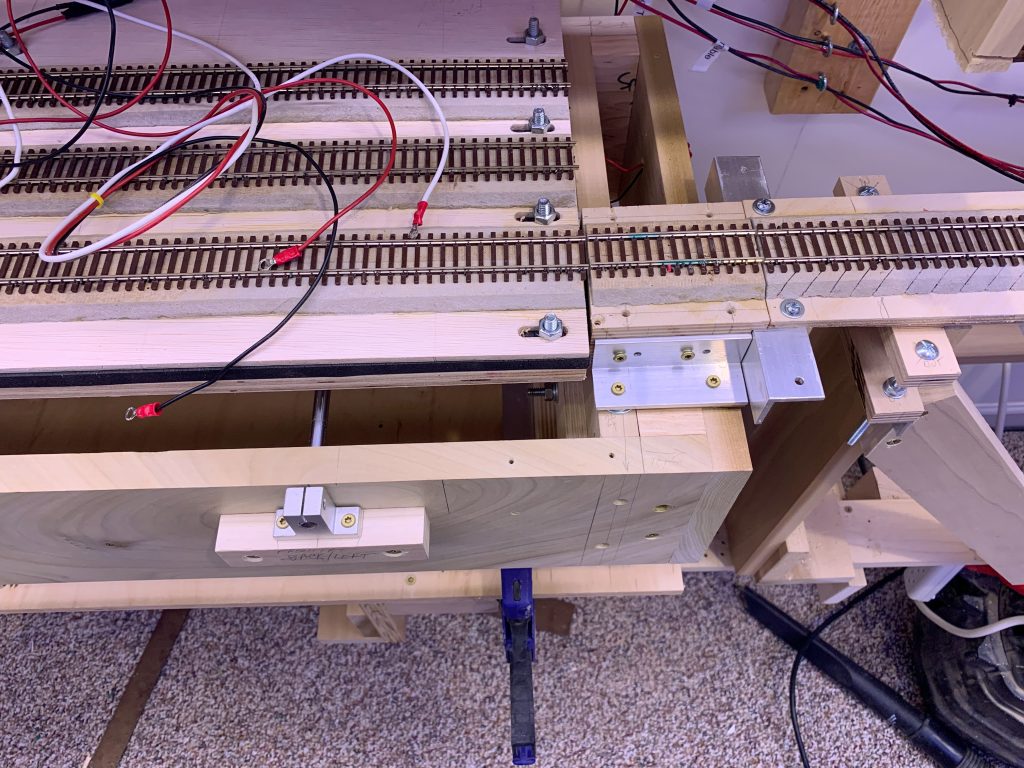
Final Installation
With the help of a friend, the entire table is moved so that it sits on a plywood floor, positioned below the level of the layout. The unit is moved up and over to align with the existing layout. It is attached with screws and is bolted to the plywood floor. After hooking up the control system, it’s ready for use.
