Benchwork Risers & Cleats
With the joists in place, I installed as many riser/cleat pairs as I needed to support the entire subroadbed but I didn’t just start whacking wood. I started at a point in the layout that I knew I could get an accurate height measurement. Because I had used 3rd PlanIt to design my layout, I could go back to the digital track plan and select any point on my layout and get its height.
I began at one extreme end of the layout and got a height from the track plan for an easily locatable spot on the layout. I wrote that height on the subroadbed at the proper spot. I repeated this process at enough spots to get proper support throughout the layout.
I didn’t need to be that exact on most of the measurements as the subroadbed will follow its natural rise and fall. I tried to be as precise as possible at the highest and lowest parts of the layout, and where long stretches of level track began and ended.
With the subroadbed marked up, I would build a riser/cleat pair to the proper height to support the subroadbed at that height at each marked location.
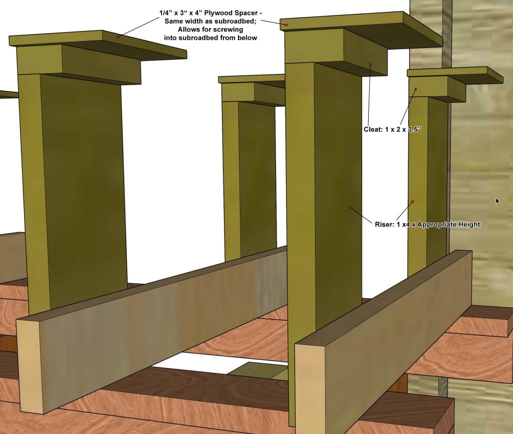
The image below shows a bunch of riser/cleats assembled and screwed in to the joists without any subroadbed yet installed. This was done to show what the riser/cleats look like. In real life, I actually placed the subroadbed on the joists first and then gradually raised it, section by section, by installing the riser/cleats.
In this drawing, you can see the details of the riser/cleat pairs. The 1/4″ thick plywood spacer is necessary to provide enough thickness to secure the subroadbed to the cleat. I made my spacers 4″ wide, which exactly matched the width of my subroadbed.

