Trackwork Subroadbed
Creating Subroadbed From CNC-Cut Sheet Material
On previous layouts, I transferred the track plan to sheet material, cut out the pieces and fit them together. It was hard, dusty work; I had to work with bulky, heavy plywood; it took hours to do and, for all that, my end results were always a severe disappointment. Things never really fit as well as I hoped.
One of the benefits of using 3rd PlanIt software is that you can either:
send your track plan to El Dorado Software (the maker of 3rd PlanIt) and he will cut out the pieces for you
-OR-
generate cutting instructions that can be used by a CNC router and either cut the pieces yourself or have someone do it for you.
I chose to have Randy Pfeiffer, the owner of El Dorado Software, cut the pieces for me. I felt it was worth it to get high grade 1/4″ Baltic Birch plywood segments, engraved to the exact specifications of the track plan, that fit together very tightly. Even though the subroadbed is 1/4″, because it’s Baltic Birch, it is plenty stiff and strong. I put risers at 16″ intervals and it’s solid as a rock. This illustrates the benefits of sometimes spending some extra bucks because it got me way down the road quicker and the end result was far superior to the alternative.
If you aren’t interested in using CNC-cut subroadbed, stop reading. If you’re interested in the approach I took, read on.
I got a quote from El Dorado and compared that with:
- the cost to have my full-sized track plan printed at the UPS store,
- the cost for good quality plywood,
- the effort and frustration of tracing the track plan, cutting out the pieces and fitting them together
- the wasted plywood from my efforts.
Ordering the Subroadbed Pieces
I emailed my track plan file to El Dorado. Randy reviewed my plan and pointed out a couple of major flaws that I simply missed. Once all was good, he produced all the subroadbed for the layout.
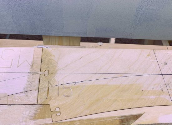
I requested engraved track centerlines in every piece. Each piece is always engraved with a unique ID, which matches back to your track plan, and it fits to its neighbors using a notch and tab mating setup that insures the pieces fit VERY snugly next to each other.
Assembling the Subroadbed Pieces
I placed all the pieces next to each other, without joining anything, to see how the pieces would fit. I only glued a given piece to 1 other piece at a time. I started by gluing up as many 2-part pieces as possible.
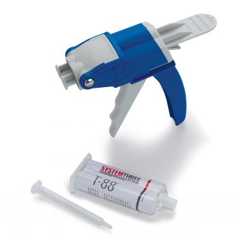
Gluing Process
I dry-fit 2 pieces together and drew pencil marks to show the boundaries of where the epoxy might ooze out to (about 4″ on both sides of every place where the 2 pieces touch).
I got at least 2 good sized clamps and sometimes more. I cut (or re-used) 2 pieces of plywood that each were at least a bit larger than the area that would contain the glue.
I tore off 2 pieces of wax paper, each more than large enough to cover the the potential glue areas; you want all glue to be covered with wax paper at the end of the day.
I placed 1 of the 2 pieces of clamping plywood on a table and covered it with one of the pieces of wax paper.
On one of the pieces, I applied a healthy amount of T-88 to all edges that would touch the other piece (and ONLY those areas). I placed that “wet” piece on the wax paper and then joined the 2 pieces, mating the tab(s) into the notch(es). To keep the epoxy off my fingers, I used more wax paper as a finger shield. I then applied a bit more epoxy along the joint to make sure all gaps would be filled.
I placed the other piece of wax paper on top, placed the other piece of clamping plywood over the wax paper and firmly tapped it with a hammer to insure that the top surfaces were perfectly even with each other. I temporarily removed the top clamping plywood and wrapped the wax paper around the edges to catch any drips. I made sure that all epoxy was wrapped in wax paper and that none would seep onto the plywood clamping pieces. I re-placed the second piece of plywood on top and used the clamps to put uniform pressure on all glued surfaces, especially the joint.
I let each glued joint cure for at least 24 hours. I removed everything and the 2 pieces had a super strong joint and the top was quite smooth.
I joined the 2-part pieces in the right order to gradually make bigger and bigger pieces. Eventually, I needed to place the larger pieces onto the benchwork. It’s not likely going to be possible to wait until you have just 1 big piece before you put it on your benchwork.
I didn’t need to place the pieces in their final location, just pretty close. Using the track plan, I determined where a few key track segment points needed to be located. I set them at the proper elevation. Then I gradually attached the larger pieces until I had all of the upper level as one piece. I made sure that the whole piece was correctly located in the x-y locations and then I set the elevation for all pertinent points. I then attached the lower level segments to the upper level, set those elevations, and I was done.
Progressive Glue-up
I joined the 2-part pieces in the right order to gradually make bigger and bigger pieces. Eventually, I needed to place the larger pieces onto the benchwork. It’s not likely going to be possible to wait until you have just 1 big piece before you put it on your benchwork.
Final Placement & Attaching to Risers
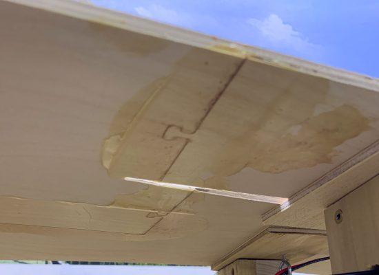
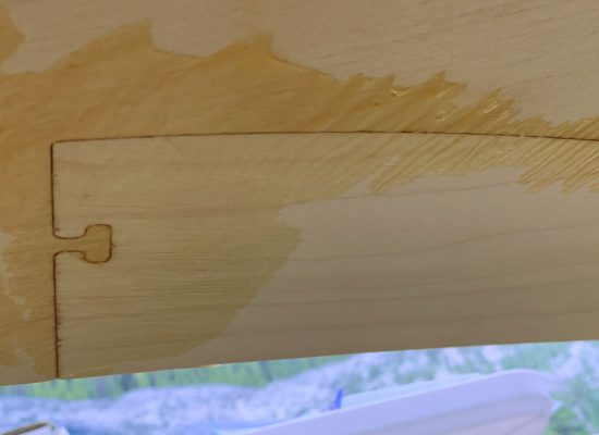
I didn’t need to place the pieces in their final location, just pretty close. Using the track plan, I determined where a few key track segment points needed to be located. I set them at the proper elevation. Then I gradually attached the larger pieces until I had all of the upper level as one piece. I made sure that the whole piece was correctly located in the x-y locations and then I set the elevation for all pertinent points. I then attached the lower level segments to the upper level, set those elevations, and I was done. The photos below show some of the subroadbed pieces in their final position.
One final note for transparency. Elsewhere on this website, in the description of how to print 1:1 PDF’s, I said that I printed the “giant” diagrams at the UPS store and taped them into a giant composite. I did do that early in my development plans, thinking that I would transfer the drawings to plywood and cut them out as I’d done on previous layouts. After printing the diagrams, I found out, to my dismay, that I had to change my plans to correct some serious errors. By then, I understood the value of the CNC-cut pieces and thus switched to using this technique.
