Ceiling Grids
Inside Runners
Just as I installed flat aluminum bars on the outside of the frame to provide a mounting surface for the valance skin, I also installed flat aluminum bars, albeit a bit wider, on the inside of the frame to provide a mounting surface for the ceiling grids.
The flat bar was first curved gently to approximate the bends in the valance frame.
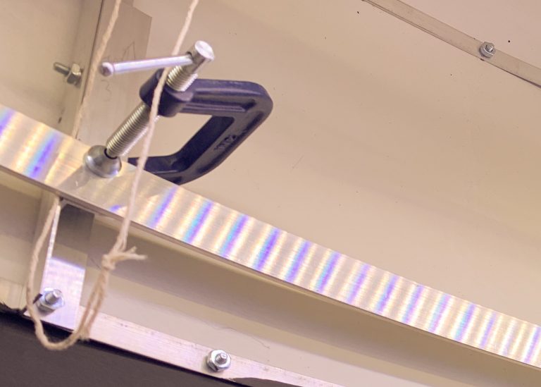
I needed some way to ensure that all wall moldings were at the same height. So, I bolted short pieces of aluminum angle to the vertical members such that the bottom of the short piece was at the correct height. These would match the height of some pencil marks I’d put on the backdrop backer boards.
The aluminum bar was moved off the string support and over to the newly-mounted short piece of aluminum angle. It was clamped in place and then bolted in place with screws/nuts.
To splice 2 pieces of inside runners, I cut a piece of the same material about 5″ long and bolted it to both pieces with 4 screws; 2 on each piece.
Wall Molding
Wall molding is L-shaped girders that attach to a vertical surface and allow the lighting panels to sit on the inside lip. If all you have is straight edges, you can use the metal wall molding found at the big box stores.
I have lots of curved walls and found that the Trim-tex Flex Grid Angle product was a superior choice. To maintain a consistent look, I used that product for all of my wall molding, even though many areas were actually straight.
Click here to read an excellent, detailed tutorial on using Trim-tex Flex Grid Angle on another layout. What follows is a high-level summary of my installation steps.
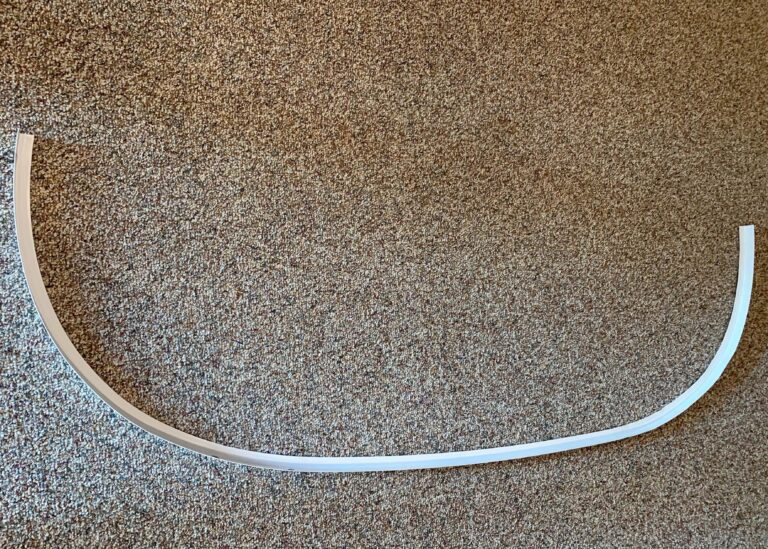
I clamped the section of Flex Grid Angle to the bottom of the backdrop to get the correct curvature. I put the product behind the backer board, then a strip of scrap masonite behind that. Then, I clamped everything together. This prevented warping the vertical part of the product.
The horizontal lip of the material initially looks wrinkled or warped. I used a heat gun to gently heat up the molding. I waved the gun around to avoid prolonged heating of any one one spot but I needed to heat up the entire curved area until it got too hot to touch. It’s a bit scary but I never caught anything on fire. The horizontal lip got hot, a bit soft and flexible but the waviness went away.
I let the Flex-trim product cool completely before I released the clamps. While cooling, the horizontal lip gets stiff again (as well as the vertical part) and the whole piece will then retain the new curve. While the product is truly impressive if the curvature is not too severe, even on really tight curves, the amount of leftover wrinkles is more than acceptable.
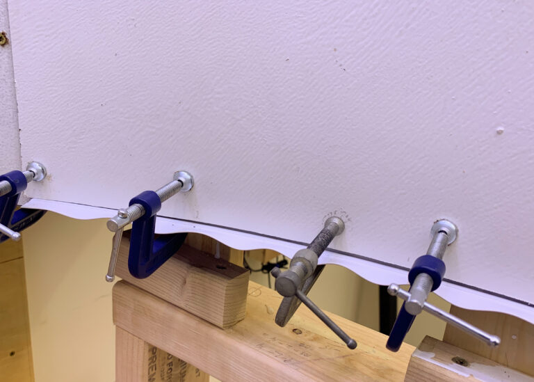
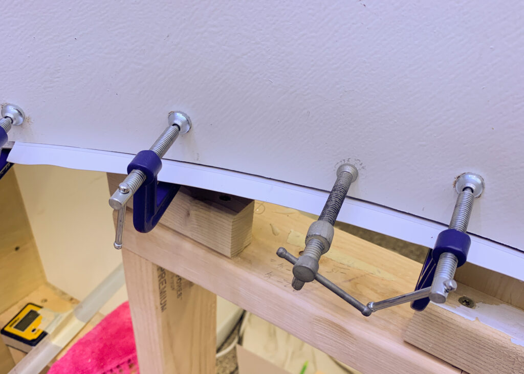
On the backdrop backer board, I first marked where the bottom of the wall molding needed to be. I also marked where each piece of wall molding was to start and end. Since I had clamped the wall molding to the bottom of the backer board to form it into its shape, it was easy to shoot a line up from the bottom to the top to mark those boundaries.
An 8′ length of wobbly Flex Grid Angle is impossible to handle with less than 6 hands. I again used the string hoist technique to get each length close to its final position and then secured it with screws or screws/nuts.
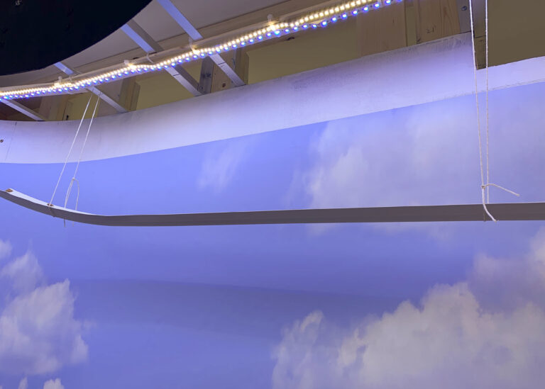
To fasten the wall molding to the inside runners, I clamped the wall molding to the inside of the runner and then used screws/nuts to secure them. To fasten the wall molding to the backdrop backer board, I simply used torx-head screws.
I made no attempt to splice the wall molding ends. It is important to make sure that the last screw at each end of a molding piece is close to the end of the material. I tried to minimize the number of butt ends but when they occurred, I cut the ends as cleanly as possible. The final project is way overhead and any small imperfections are very hard to pick out. Anyone who does gets track cleaning duty.
Marking the Ceiling Grids’ Locations
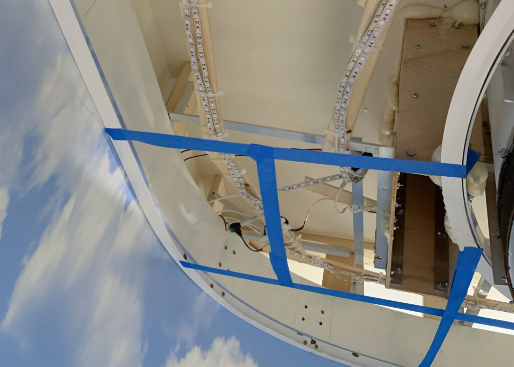
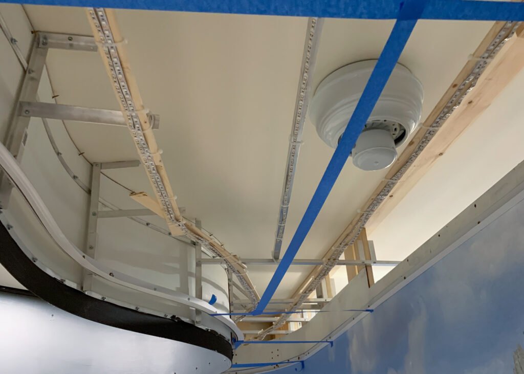
Normally, when laying out grids, you DON’T use blue tape. Rather, the vendor has very good steps to help you layout your grids to be level and perpendicular. I had to invent a new process because of the small area and the multitude of curved walls. For better or worse, I committed to custom cutting every lighting panel. This freed me to place the grids anywhere I wanted. Still, I was able to use full size panels in a few places.
I took rough measurements of the area defined by the edges of the wall moldings and made a rough sketch of the area on paper. Then I laid out how I thought the panels should be installed, keeping in mind the size of a full panel.
With an initial plan in mind, I used blue painter’s tape to lay out where the metal ceiling grids would go. Most areas were easy to define and could absorb any small changes later. I had to concentrate on just a few areas to make sure that:
- It was no larger than the size of a full panel
- It was not so small or too oddly shaped as to be too fragile
- It was actually possible to maneuver a panel into that position
That last requirement was the one that kept giving me fits.
Installing the Ceiling Grids
Normally, the metal grid members “lock” into place because of built-in tabs and slots. But because I was using plastic wall molding and had mostly just short runs, I needed to use rivets to hold the grid parts together.
For my use case, I began at one end and used the blue tape to tell me about where a grid should be placed. I mostly used what are called “cross grids” because most pieces were short and carried little weight.
For each grid, I cut it to length. Then I placed each end over a wall molding ledge. I ensured that things were square and then used some “grid clamps” that are specially made for this purpose to clamp the cross grid to the 2 wall moldings. I used another special tool to punch a hole through both the grid and the molding and then used a riveter to put a rivet into the hole. This secured the grid member to the wall molding. You can see a rivet at each end in the image below.
I used this last-installed grid as a starting point for the next area that would be bounded by ceiling grids. Rinse and repeat!

